SAE Toyota Journal About the Importance of PCV Systems in Modern Engines Summarized by Dezoris:
What does the PCV System Actually Do?
The PCV system is designed to recycle engine blow by gasses back into the intake for emissions purposes.
However to do so it requires a variable PCV valve because the amount of blow by gas coming out of the engine down the PCV hose is not always equal to the amount of vacuum at the intake manifold.
So the PCV valve is opened and closed based on the amount of vacuum at the intake manifold and the amount of blow by gasses being vented. This helps to equalize the vacuum and gas pressure to insure smoother engine operation. The air to fuel ration and the tuning for that system takes into account PCV vacuum and air flow.
1. Full Throttle and high RPM = Lower Intake Manifold Vacuum, High Engine Blow By.
In this condition the PCV Valve is forced full open. If there is too much blow by then the breather hose will also be used to vent into the intake hose. This will only occur under high load situations.
2. Lower Throttle, Cruising = Moderate Intake Manifold Pressure, Lower Blow By.
In this condition PCV Valve is half open
3. Idle or De-Acceleration = High Intake Manifold Pressure, very low blow by.
In this condition the PCV valve is virtually closed.
Side Effects and how to Test for Issues:
PCV valve and PCV Hose:
PCV Valve is engine specific to engine tuning, if you use the wrong valve or it becomes clogged the air/fuel ratio computation tends to run rich. Rough Idle, stalling or performance issues could also occur.
Testing for blockage or faulty PCV Valve:
First you want to plug in your OBDII scanner and monitor engine RPM.
Once the car is fully warmed up or your coolant reaches 170 Degrees or higher, clamp off your PCV tube from the PCV valve to the intake manifold. Once blocked engine RPM should drop 50-100RPM.
If it does not you may have a damaged PCV hose or bad PCV valve or the system is clogged.
In this case you may see issues with rough idle or some drivability issues. The PCV line is under vacuum, not the breather hose.
A plugged PCV line will cause higher oil consumption in the crank case.
Breather Hose:
Its primary design is to vent excess blow by that the PCV valve and hose can't pass. Usually only under high load.
If the breather hose is clogged or blocked it will cause higher pressure inside the crank case which can cause higher oil consumption and or more unburned fuel which can contaminate the oil. However a leak in the breather hose wont generally cause any issues.
Used Oil Analysis:
Sending out used oil will help to show if there is a higher level of fuel in the oil which could also track back to a faulty PCV system.
Oil in Intake Tube:
Usually is caused by a faulty PCV valve stuck open restricted PCV hose which will cause more oil in the breather line.
Installation Preparation
Purpose: To prevent oil, oil mist and moisture flow back into the intake manifold and intake valve train.
Long Term: Prevents oil build up on valve train and intake manifold that will bake on and cause massive carbon deposits, which can cause performance and efficiency issues prevalent on direct injected engines. (Large discussion about the issue in direct injected Audi's http://www.audizine.com/forum/showth...up-Megathread?)
Difficulty Level: Easy
Time to Install: 1 Hour if you are not making a bracket 3 Hours if you are making a bracket 12 hours if you use narcotics
##################################################
Parts Needed:
HOSES:
2 Feet of 1/2" ID PCV Tubing (Gates Safety Stripe II - Fuel Line/PCV/EEC Hose Part # 2700 6)
2 Feet of 11/32" ID PCV Tubing Goodyear PCV (65119)
OTHER PARTS:
QTY 2: 11/32 - 3/4" Hose clamps of your choice
QTY 1: Radium Universal Catch Can
QTY 1: 0.5" OD Barb
QTY 1: 0.425" OD Barb OR 90 Degree 2 Piece 0.425" (Both Barbs are slightly larger than the hose.)
QTY 1: Aluminum Strip (Cut down to 10" length)(Home Depot) (Crown Bolt 1 in. x 48 in. Aluminum 1/8 in. Thick Flat | Model Number: 44660)
QTY 2: Pan Head Screws to secure bracket to aluminum
QTY 2: Pan Head Fastening Nuts QTY 1: Loctite 6-ml Threadlocker 242 (Blue)
Tools List:
- Flat Head Screw Driver
- Phillips Head Screw Driver
- Needle Nose Pliers
- 3mm Allen Key for Radium Screws 10mm Socket with Extensions
- Bench Grinder (if you cut your own bracket)
- Sheet metal Sheers, Bolt cutter, Band Saw, Jig Saw (Whatever you have to cut Bracket)
- Vise to help bend your aluminum
- Pliers (To tighten Barbs)
- Vise grips (To bend aluminum to shape)
- Spray paint, or vinyl (or nothing if you want your bracket silver)
I chose the Radium can for a few reasons.


Installation:


2. Attach the .5" Barb to the outlet port (Middle of Can)
3. Insert 3 stainless steel filters in top port of can.


4. Attach the .4" Barb to the inlet port (Top of Can)
5. Attach can to supplied Radium bracket to assure it fits and then remove it from the bracket.
6. Cut your aluminum strip down to roughly 16"
7. Scribe the marks on the aluminum piece.

8. Drill holes into bracket using the correct drill bit for the screws you purchased.
10. Spray your bracket black or cover with vinyl. (OPTIONAL)
11. Secure your bracket the the Radium can bracket. (Ignore bracket length in picture)

12. Remove the two 10mm screws on the air pump/noise generator bracket.

13. Test fit the length of the aluminum so you can bend the metal to shape to fit.
14. Remove the aluminum from the Radium bracket and bend to shape, using small vise and vise grips.
15. Drill hole at end of aluminum to fit the 10mm mounting screw from air tube.
16. Test fit your custom bracket make sure you have enough clearance and the can sits level.
17. Secure the Radium Can to the bracket with supplied Allen Screws using blue thread lock on the screws.

18. Finish final assembly making sure you use thread lock on all your bolts. (NOT THE BARBS)

19. Snaggle the bracket into place and re-tighten the two 10mm bolts back into the air hose/noise generator bracket. Bend your aluminum as needed.
20. Remove the top plastic cover from the engine that says Toyota, Subaru.
21. Underneath remove the PCV hose. (The one on the left with no hose clamp)
22. Follow the PCV hose down and remove it from the PCV valve. (Just pulls off, don't complain)

PCV VALVE AND HOSE

23. Grab 18" of 1/2" PCV hose and connect it from the intake manifold and then to the outlet of the catch can push it on there, use hose clamps if you want to.
24. Grab 18" of 11/32" PCV hose and connect it from the PCV valve to the catch can inlet. Don't be a chud, if it feels loose use hose clamps.

25. Check tightness and all hoses.
26. Re-install plastic cover.
27. Look at that you installed it!!!!

FINAL NOTES SHUT UP AND LISTEN!!!
Q&A
Q. What no breather tube can?
A. You don't need a can for the breather tube unless you are on the track all day every day or you use I forced induction. The PCV system is where 95% blow by goes. Still concerned? Check the intake tube at thethrottle body. If there is oil there, well you need to get a can for the breather tube.
Read the PCV info first post for more details.
Change in Barbs FYI - Choose the standard or 90 Degree Two Piece Barb.
- I used to own a Lotus and Radium was one of those companies who put quality over quantity.
- I already had the can from my previous car and knew it worked.
- I want an OEM looking piece that will last the life of the vehicle.
- Most importantly, there was engineering behind it, design, flow testing race testing and more. It's not a generic product.
| This image has been resized. Click this bar to view the full image. The original image is sized 972x629. |
Installation:
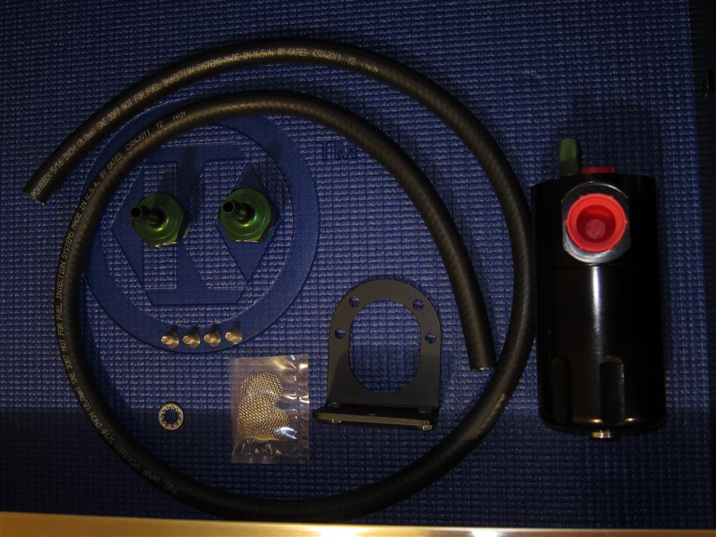
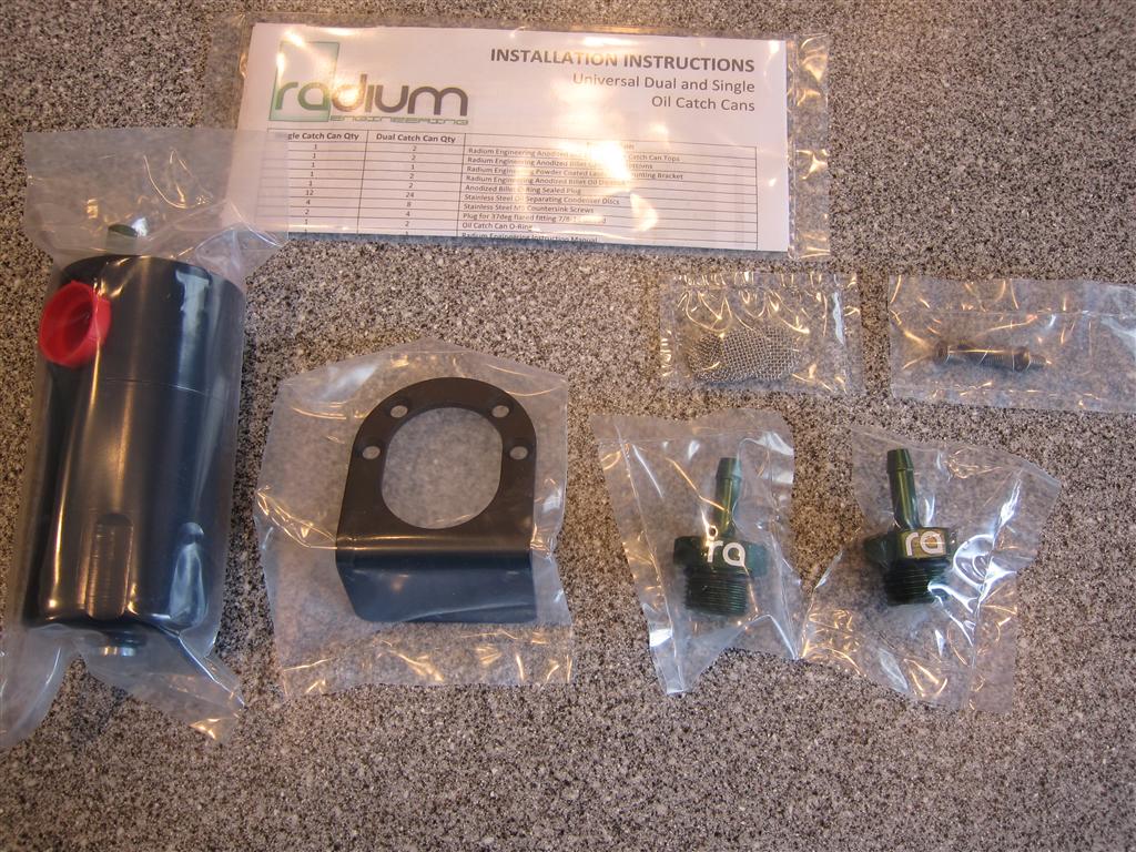
- layout contents of can.
| This image has been resized. Click this bar to view the full image. The original image is sized 1024x768. |
2. Attach the .5" Barb to the outlet port (Middle of Can)
3. Insert 3 stainless steel filters in top port of can.
| This image has been resized. Click this bar to view the full image. The original image is sized 1024x768. |
| This image has been resized. Click this bar to view the full image. The original image is sized 1024x768. |
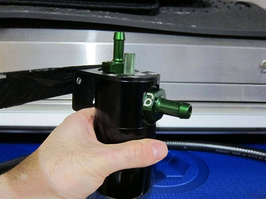
4. Attach the .4" Barb to the inlet port (Top of Can)
5. Attach can to supplied Radium bracket to assure it fits and then remove it from the bracket.
6. Cut your aluminum strip down to roughly 16"
7. Scribe the marks on the aluminum piece.
| This image has been resized. Click this bar to view the full image. The original image is sized 1024x768. |
8. Drill holes into bracket using the correct drill bit for the screws you purchased.
10. Spray your bracket black or cover with vinyl. (OPTIONAL)
11. Secure your bracket the the Radium can bracket. (Ignore bracket length in picture)
| This image has been resized. Click this bar to view the full image. The original image is sized 1024x768. |
12. Remove the two 10mm screws on the air pump/noise generator bracket.
13. Test fit the length of the aluminum so you can bend the metal to shape to fit.
14. Remove the aluminum from the Radium bracket and bend to shape, using small vise and vise grips.
15. Drill hole at end of aluminum to fit the 10mm mounting screw from air tube.
16. Test fit your custom bracket make sure you have enough clearance and the can sits level.
17. Secure the Radium Can to the bracket with supplied Allen Screws using blue thread lock on the screws.
| This image has been resized. Click this bar to view the full image. The original image is sized 1024x768. |
18. Finish final assembly making sure you use thread lock on all your bolts. (NOT THE BARBS)
| This image has been resized. Click this bar to view the full image. The original image is sized 1024x768. |
19. Snaggle the bracket into place and re-tighten the two 10mm bolts back into the air hose/noise generator bracket. Bend your aluminum as needed.
20. Remove the top plastic cover from the engine that says Toyota, Subaru.
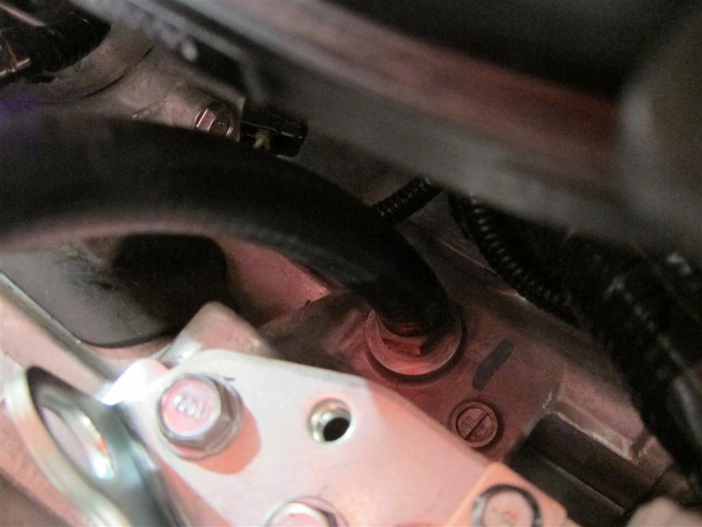
21. Underneath remove the PCV hose. (The one on the left with no hose clamp)
22. Follow the PCV hose down and remove it from the PCV valve. (Just pulls off, don't complain)
| This image has been resized. Click this bar to view the full image. The original image is sized 1024x768. |
PCV VALVE AND HOSE
| This image has been resized. Click this bar to view the full image. The original image is sized 1024x768. |
23. Grab 18" of 1/2" PCV hose and connect it from the intake manifold and then to the outlet of the catch can push it on there, use hose clamps if you want to.
24. Grab 18" of 11/32" PCV hose and connect it from the PCV valve to the catch can inlet. Don't be a chud, if it feels loose use hose clamps.
| This image has been resized. Click this bar to view the full image. The original image is sized 1024x768. |
25. Check tightness and all hoses.
26. Re-install plastic cover.
27. Look at that you installed it!!!!
| This image has been resized. Click this bar to view the full image. The original image is sized 1024x768. |
FINAL NOTES SHUT UP AND LISTEN!!!
- If you drive for economy drain the can every oil change 3000-5000 miles
- If you drive agressive street only, check the can level every 2000 miles.
- If you do auto and aggressive street driving check every 1000 miles.
- If you track the car, check after each session.
Q&A
Q. What no breather tube can?
A. You don't need a can for the breather tube unless you are on the track all day every day or you use I forced induction. The PCV system is where 95% blow by goes. Still concerned? Check the intake tube at thethrottle body. If there is oil there, well you need to get a can for the breather tube.
Read the PCV info first post for more details.
Change in Barbs FYI - Choose the standard or 90 Degree Two Piece Barb.
